Dirty Doper
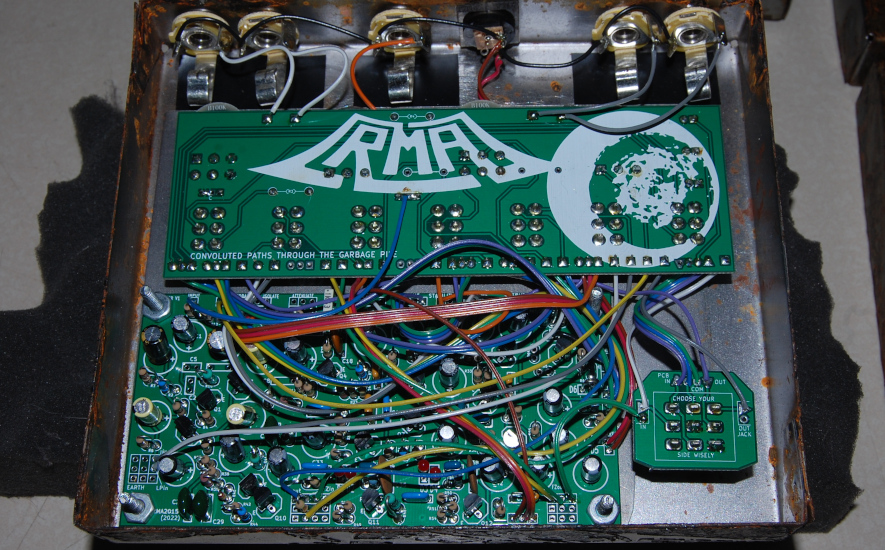
The RMA Dirty Doper was my first foray into a purpose built distortion circuit. It is comprised of a collection of stages pieced together like a patchwork quilt, and the actual execution of the build as originally designed is a horrific undertaking rife with myriad layout mistakes. Take, for example, my choice to allocate the entire perimeter of the PCB as wiring connection points for switches, pots, and connectors; resulting in a rat's nest of an installation in its final form. It is, to put it succinctly, an embarassment on the technical front.
Furthermore, for all the complexity in its realization, it does not offer the range of sound I would expect given the quantity of controls. Perhaps I am being overly critical of the design. I have personally been underwhelmed by it on numerous occasions, only to the hear it under someone else's touch and again understand the appeal. It can be said that the Dirty Doper is selective of the environment in which it operates, for an electronic device it has personality.
All of this is to explain why I have been reluctant to maintain consistent production on this design. The complexity of building followed by my sense that there is so much room for improvement is something of a non-starter. This is why a Mk2 is under development. Anyway, on with a description of the circuit and controls, that are applicable only to the initial design.
Initial gain stage is loosely based on a section of the Neve BA283 and exploits both inverting and non-inverting output paths, henceforth referred to as lower and upper respectively. Upper path feeds a fuzz cell based upon the Roland AF-100 BeeBaa (minus boost, only retaining the switched tone selection), and one side of a transistor differential pair post "volume control" in the form of clockwise position of the blend knob. Lower path feeds a bypassable fixed frequency low pass filter, a bypassable fuzz cell based on the PNP version of the 1st generation EH Big Muff, and a polarity selector (in that order) feeding the other side of the transistor differential pair post "volume control" in the form of counter-clockwise position of the blend knob. The transistor diff pair that is doing the summing of upper and lower paths sits on a variable tuned circuit, the output of the diff pair feeds a final transistor stage to drive output.
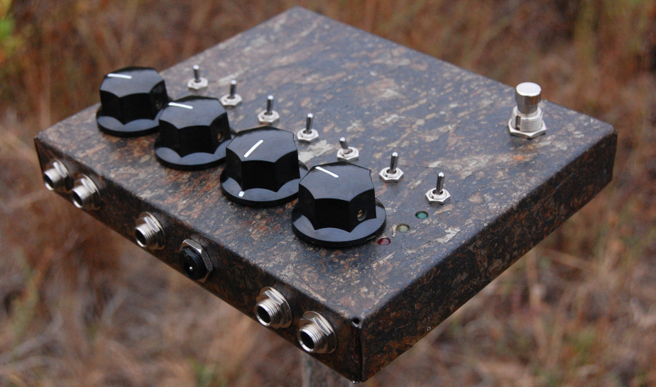
Included in that morass is a variable brute force voltage regulator that can be set to follow external CV and starve the rails, and an output mode that includes a natural setting, a feedback setting, and a dark setting. Standard with the Dirty Doper is a pair of inputs and a pair of outputs: the inputs see 10K separation from one another while the output jacks are in parallel, this is in support of feedback loops or parallel processing without special cables. Furthermore, the green LED will always light when power is applied.
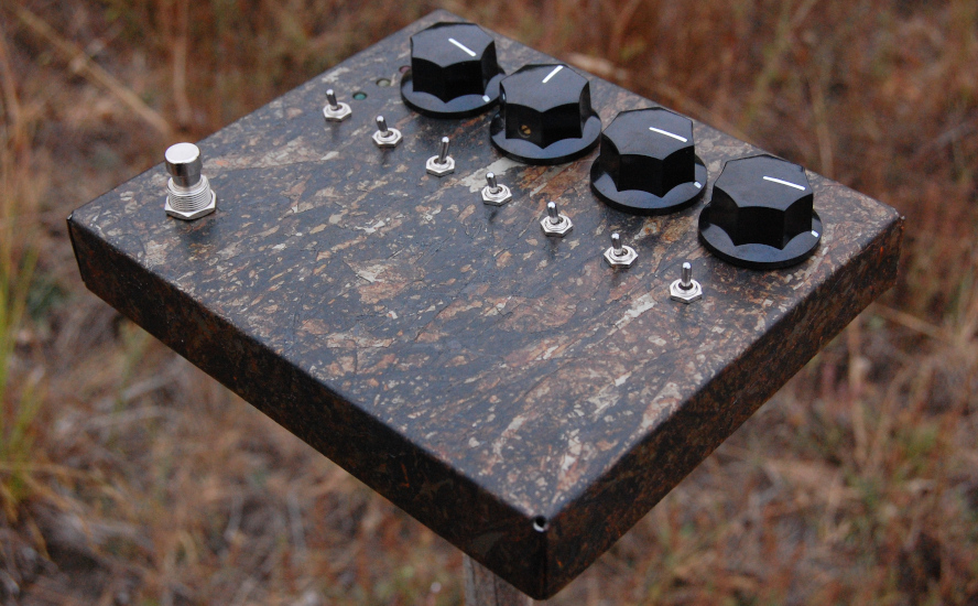
- Leftmost knob controls GAIN and is nested within the initial gain stage.
- Center-left knob is the BLEND control.
- Center-right knob is the STABILITY control, and is situated "beneath" the differential pair.
- Rightmost knob controls output VOLUME.
- Leftmost switch (#1 reading left to right) actuates CV mode when bat UP. This lights the yellow LED. please note that the effect will absolutely not pass signal unless several volts is applied to the CV input - this revision allows a primitive control that does not have any offset or scaling to support 0-low voltage CV sources.
- Switch #2 is fuzz bypass on the lower path, bat UP = fuzz engaged.
- Switch #3 is low frequency filter, bat UP = treble good, bat DOWN = bass emphasis.
- Center switch #4 selects upper path fuzz tone.
- Switch #5 is a three position switch that selects the voicing of the tuned circuit that works in tandem with the STABILITY control.
- Switch #6 is the lower path polarity selection.
- Rightmost switch #7 is the three position output mode switch.
Bat DOWN = dark, bat MID = normal, bat UP = feedback - Red/yellow/green stoplight LED stack indicates the following when lit:
RED = effect engaged, YELLOW = CV mode active, and GREEN = DC power is applied.
Mk2 design criteria will include (but is not limited to) more latitude with respect to where each individual stage falls with respect to the upper & lower paths, a reworked gain stage, and more sophisticated CV handling circuitry with provisions to manually control the levels without reliance on external devices.
DEVICE
Dirty Doper
TYPE
Fuzz / Distortion
STATUS
In redevelopment, Mk1 available by request
PRICE
$375 USD plus shipping